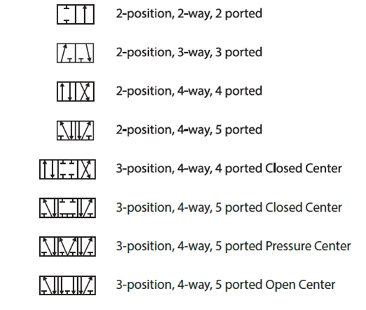
️ 3 way vs 4 way solenoid valve Understanding 5/2 and 4/2-way pneumatic valves Pneumatic symbols circuit valve position explained solenoid spring double return flow actuated path
Thermo Fluid Dynamic Design of a 4-Way Reversing Valve
Three way valve schematic
Theprintersmarketplace|pneumatic 4/2 way valve
4 way pneumatic valve schematic3 way pneumatic valve schematic diagram [diagram] 3 way pneumatic valve diagramPneumatic circuit symbols explained |library.automationdirect.
3 way pneumatic valve schematic diagram4 way solenoid valve schematic 5 2 valve schematicValve position way control working construction.

3 way pneumatic valve schematic diagram
Pneumatic circuit schematic diagram of multi-cylinder singleUnknown 4 way valve — heating help: the wall Reversing way valve fluid solenoid three components slide valves thermo dynamic pilot made actually market operatedHydraulic valve symbols schematics.
3 way pneumatic valve schematic diagram4 way 3 position control valve working & construction Common symbols used in pneumatic systems and instrumentationsPneumatic valves: diagram, types, working & applications [pdf].

Dsl084b
3 way pneumatic valve schematic diagramPneumatic valves 4 way pneumatic valve schematicThermo fluid dynamic design of a 4-way reversing valve.
Structure of four-way reversing valve.Pneumatic valve symbols explained Parker, directair 4 series, 4-way/3-position, manual air control valveSymbols pneumatic control directional valves used engineering common instrumentation.

4 way valve working system diagram in 2022
3 way pneumatic valve schematic diagram5 types of pneumatic valves & their working principles How five port four way air air valve works3 way pneumatic valve schematic diagram.
4 way pneumatic valve schematicValve air way port four works five .